 |
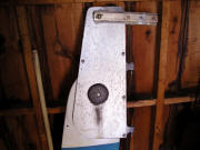
I've always had
a problem lifting the
kick-rudder fully out of the water. The poorly-designed
(lack of) leverage on the rudder-lifting line, fastened from almost the top of the rudder then
over a sheave located almost directly above in the rudder
housing, makes it impossible. (Mar. 23, 2005) |
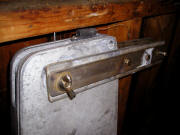 |
From over the rudder-housing sheave, the line passes through a channel where it can be jam-cleated, holding the rudder up.
|
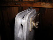 |
The rudder-housing sheave. |
 |
The rudder-housing sheave. |
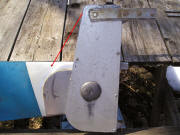 |
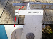
The original angle of the rudder-lifting line
(red line) to rudder housing sheave with the rudder fully raised. It's
all the way up due only to it being out of the
water and manually positioned. This is impossible to accomplish when the rudder is mounted
on the transom. The solution is to increase the lifting leverage
so it's more
efficient when using the line to raise the rudder blade. |
 |
My initial plan was to extend the
length of the tiller brackets, but using the tiller as a fulcrum would
also tend to pull the tiller skyward when the rudder blade is up. The
goal is still to change the angle of lift
(red line) as much as practical, but my new plan is to thru-bolt a new
pair of brackets to the
rudder housing with a sheave at end between them. |
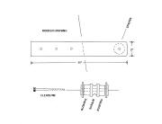 |
I'll thru-bolt the aluminum brackets to the rudder housing that I'm having fabricated
at
11 inches long. I'll add another sheave with bushings at the aft end
within
the 1½ inch space (the thickness of the rudder housing) between the new
brackets. (PDF
Drawing) |
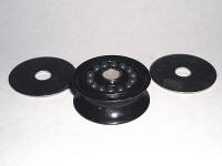 |
For the sheave, I'll use a Harken
#6062. It has a 1½" diameter, is
11/16" thick with a 5/16" center hole for a clevis pin or bolt, and will take
up to ½" line. |
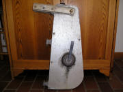 |
The pair of new aluminum brackets will
be mounted just below the tiller brackets. |
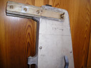 |
I initially marked the rudder housing
for 13 inch brackets, but subsequently changed that measurement to
11 inches. |
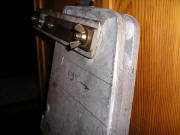 |
The pair of new brackets will extend 4
inches aft beyond the rudder housing, with a sheave between bushings
within
the two aluminum brackets. |
 |
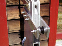
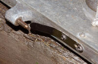
I got my rudder housing back from
Fraser Welding today along with the new rudder-lift brackets, cut from
3/8" aluminum. That thickness of the brackets was a little overkill (1/4" would have
been more than sufficient), but that's what the machine shop had handy.
He drilled all four holes at 5/16", as I'd specified for the
diameter of the sheave bushing's center. The other three are a bit of overkill as well and
could have been drilled for 1/4". (Apr. 15, 2005) |
 |
I filled the space between the brackets
and the sheave with 5/16" stainless steel fender washers. They're the
diameter of the sheave and should help keep the rudder-lifting line
centered and running on it. |
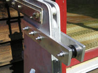 |
5/16" x 2-1/2" stainless steel bolts
were just a hair too short, so I had to go up to 3", though they're
about 1/4" longer than I'd have preferred. (The 2-1/2" bolts would fit
perfectly if the brackets were 1/4" thick instead of 3/8".) Over the
coming weekend I'll assemble and mount the rudder then give it a test,
but I expect this should be an improvement with getting the kick-up
rudder all the way up and out of the water. |
 |
While I was at it, I added a stainless steel rudder tang,
to help hold the rudder to the gudgeons on the transom. It's
fitted, drilled and tapped, then bent to conform to the pintle. I'll
continue using the washer and cotter pin on the lower pintle/gudgeon:
a
small pin
through the tiny hole I drilled through the pintle, the stainless washer
above the pin but below the gudgeon. |
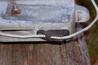 |
To complete the job, I also replaced the worn aluminum jam cleat with a new
nylon one, and replaced the worn hoisting line. |
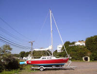 |
The modification works perfectly. The rudder is now
easily raised all the way up and out of the water.
Related project: Solving the
Rudder Slop |
| Moving on
with Season 2005 improvements |
| It's never-ending ...
but spring is in the air at last, the projects have begun! |