|
One of my early projects on Chip Ahoy
in the spring of 2003 was rewiring the electrical system, and that began
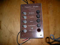
with replacing the switch/fuse panel. The original panel (left) was
seriously corroded so I removed and tried cleaning it up, but it was too far
gone. |
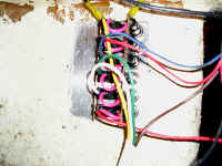 |
The original panel had only five circuit
connections, and since I planned to add an anchor light atop the
mast, a deck light at the mast spreaders, and a VHF radio, I'd need
additional connections and switches. I had to cut away a little of
the fiberglass to make the new switch panel fit. I had labeled the
wiring and drawn myself a diagram, so once mounted, I wired it up as it
had been. Then I added the new circuits I needed. |
|
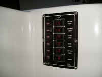
The new panel provided one extra switch.
It used lighted rocker
switches instead of toggles, which made inadvertently switching a
circuit on when stepping in or out of the cabin -- a frequent occurrence,
I learned from other Catalina 22 owners -- more difficult. The
"on" light at least indicated the circuit was active.
But I wanted a way to control 12V power to the entire panel . . . |
|
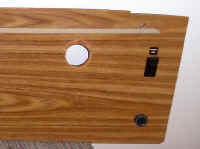
To free up another switch on the
panel, I moved the 12V master switch wiring
from the old panel to a new lighted (when on) rocker switch I mounted on the winch
panel, just above the ignition switch for the outboard's electric
starter. The leads went to the battery (which I subsequently changed to
the battery switch when I installed the second battery and battery
switch the following year). At the same time I also added a voltmeter
and the bilge pump switch to the opposite side of this panel (see
below). |
|
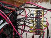
I added a buss block terminal to the
aft bulkhead between the cabin and the cockpit beneath the aft settee
seat on the port side in the cabin, one side positive the other
negative. I connected the positive side to the master switch.
Note in the center-left of this photo
and bottom-right that I labeled each fuse-holder with the name of the device it protects.
Then, if and when a circuit blows, I can more easily find its
fuse-holder in the maze and check its fuse. |
|
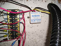
When I added a small solar
panel the following year (2004), I added a Sunguard-4 (Morningstar)
controller alongside this buss. (Its leads run from the solar panel
through the controller to the battery switch I subsequently installed.) |
|
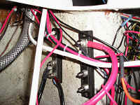
Installing the second
battery and battery switch in 2004 required two new buss blocks, one
positive the other negative. They were mounted around the corner in the
bilge from the initial buss terminal. (Their covers have been
removed in this photo.) |
|
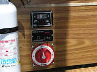
From top to bottom, the voltmeter, bilge pump switch and
battery switch.
SeaDog Voltmeter (Dual Batteries) Switch schematic
(PDF File) |
|
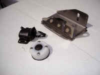
I replaced the deck-mounted (hidden)
running lights unit with the new pulpit-mounted style. I ran the wiring
through the pulpit tubes and down below deck, where I wired it into the
original embedded wiring harness. |
|
Once I'd installed the new mast wiring
harness and wired up the new anchor, deck and steaming lights, I needed
a new deck connector for the additional wires (4 altogether). After a frustrating week
fighting against two bad SeaDog connectors that kept shorting out, I
finally bought an AquaSignal deck connector that worked perfectly; it
also provided an extra (5th) wire connection should I ever need it. At this
point I also added a Blue Sea Systems cable clam on the cabin top
for the VHF antenna cable to run through into the cabin. |
|
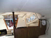
Inside the cabin, I ran the wiring along the overhead
then down into the V-berth area, then beneath the dinette area to the
switch panel. (See: preliminary deck wiring into the
cabin for more details.) I replaced all the cabin light bulbs
with halogen light conversion kits. |
|
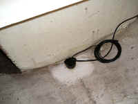
When I installed a new "fishfinder"
(we used to call them depth finders -- because we were looking for
depth, not fish!) in 2004, I epoxied it to the hull in the aft locker
beneath the V-berth and ran its cable along the same route as the mast
wiring, then up to and through the port side cabin/cockpit bulkhead out
to the cockpit. |
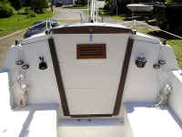
|
A view from the cockpit of the new
fishfinder mount (port side) and compass (starboard side).
|
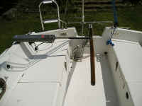
|
When I installed a new tiller
pilot, I ran its wiring aft across the transom beneath the cockpit
liner, then forward along the port side, and into the cabin. That is
still a work-in-progress,
but now that I've upgraded from two failed Raymarine ST-1000s to an
ST-2000 that works, I'll wire it into the buss terminals this season.
(Note the "cigarette lighter" receptacle I added at
bottom-right to power the handheld GPS instead of having to run off its
batteries.) |
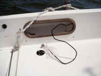
|
One of the last things I did before
heading out on my cruise up the Maine coast in August of '04 was to
wire-up the ICOM IC-M402 radio to my Garmin handheld GPS so I can use
the NMEA DSC (distress calling/position) function. It's cable runs from
the cabin out to the cockpit and connects there to my handheld GPS. I
keep its connector covered when it's not connected and sealed with a
rubber band when it's not in use, stowed away in the coaming
compartment. This eliminated the need of the "cigarette
lighter" receptacle I'd added to the bulkhead beneath this
position. (The black circular disk fastened beneath the connector is the
base for my GPS mount.) |
Lessons learned: If I
had it to do over again, I'd have done the job cleaner and reduced
if not eliminated the "rats nest" of wiring chaos.
Fortunately, I did the job and know where everything is and runs to.
Hobie Davidson sent some pretty neat aircraft-wiring sheathing
material that he used when rewiring Dick King's "Jagged
Edge," but it
was too late for me unless I want to disconnect and rewire all --
which I'm just not up to doing. Plan ahead as much as possible
before you start running wires. If you don't have to, chances
are that you'll never want to revisit this project again either.
Being a contortionist would be an
advantage when undertaking this project: most connections are
readily accessible, but not easy to work on without some serious
physical contortions. Before you get yourself into position, make
sure all tools and parts you'll need are within easy reach of your new posture.
Think ahead before you wrestle yourself into such a contorted,
immobile position -- after getting yourself there you'll want to hold it as long as you physically can!
Conclusions: Throughout this ongoing project
I've almost exclusively used 16 AWG marine-grade wiring, color-coded
when practical, and corresponding marine-grade connectors. The
exceptions were 10 AWG occasionally when it seemed prudent,
and 8 AWG when connecting from busses to the battery switch. I used 16 AWG multiple-wire sealed
cable to continue the
mast wiring harness inside the cabin to the switch panel, and 12 AWG
two-wire sealed cable for the tiller pilot from cockpit to cabin
busses. All connections are sealed with shrink-tubing. All fuse-holders are labeled with the
devices they are protecting.
The only original wiring that
remains is that which runs between the deck and the cabin overhead,
and out to the stern light. I never have figured out a means to remove
and replace it without major structural work and continue to keep my fingers crossed that it never
fails. . . .
-- MORE
CONCLUSIONS --
|